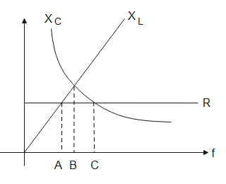
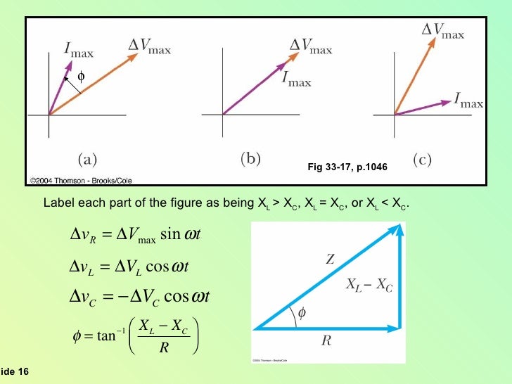
40 (a) Label The Following Figure As Being Xl > Xc, Xl = Xc, Or Xl < Xc.
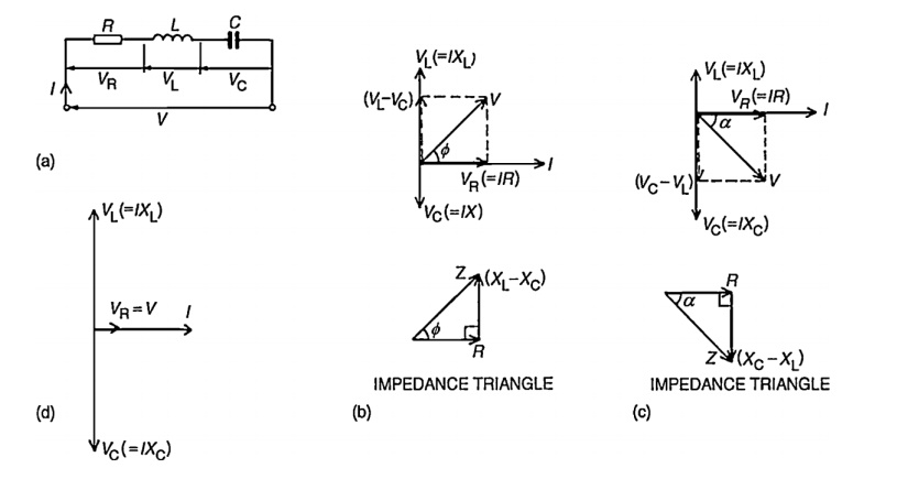
For drawing the phasor diagram of series RL circuit; follow the following steps: Step- I. In case of series RL circuit, resistor and inductor are connected in series, so current flowing in both the elements are same i.e I R = I L = I. So, take current phasor as reference and draw it on horizontal axis as shown in diagram. Step- II. Where: ƒ is the Frequency and L is the Inductance of the Coil and 2πƒ = ω. From the above equation for inductive reactance, it can be seen that if either of the Frequency or Inductance was increased the overall inductive reactance value would also increase. As the frequency approaches infinity the inductors reactance would also increase to infinity acting like an open circuit.
Question: Label the following figures as being XL > XC, XL = XC, or XL < XC (a) (b) (c) This problem has been solved! See the answer See the answer See the answer done loading
(a) label the following figure as being xl > xc, xl = xc, or xl < xc.
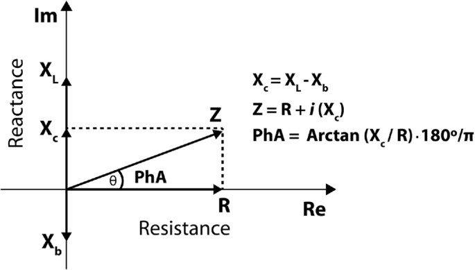
Series RLC Circuit Example No1. A series RLC circuit containing a resistance of 12Ω, an inductance of 0.15H and a capacitor of 100uF are connected in series across a 100V, 50Hz supply. Calculate the total circuit impedance, the circuits current, power factor and draw the voltage phasor diagram. Inductive Reactance, XL. Capacitive Reactance, XC. Search the world's information, including webpages, images, videos and more. Google has many special features to help you find exactly what you're looking for. What is the phase angle between the voltage across and the current through a series RLC circuit if XC is 500 ohms, R is 1 kilohm, and XL is 250 ohms? A. 68.2 degrees with the voltage leading the current; B. 14.0 degrees with the voltage leading the current; C. 14.0 degrees with the voltage lagging the current
(a) label the following figure as being xl > xc, xl = xc, or xl < xc.. Figure 8.64 For Prob. 8.3. Chapter 8, Solution 3. At t = 0-, u(t) = 0. Consider the circuit shown in Figure (a). i L(0-) = 0, and v R(0-) = 0. But, -v R(0-) + v C(0-) + 10 = 0, or v C(0-) = -10V. (a) At t = 0+, since the inductor current and capacitor voltage cannot change abruptly, Calculate the following: (a) VR0, VL0 and VC0, the maximum voltage drops across each circuit element, and (b) the maximum voltage drop across points b and d shown in the figure. Solution: (a) The inductive reactance, capacitive reactance and the impedance of the circuit are given by ()()6 11 49.0 C 100 65.0 10 X ωC π − == = × Ω (2.1) (100. Sep 13, 2021 · To verify the PSII densities, we performed sub-tomogram averaging of two adjacent PBS particles on the same linear array (indicated in the red boxes of Figure 1—figure supplement 1B,C) and generated a structure at a resolution of 15.6 Å (Figure 2A, Figure 2—figure supplement 1A,B).The recently determined 2.82 Å single-particle PBS (PDB code 6 KGX) (Ma et al., 2020) was well-fitted into. Let's take the following example circuit and analyze it: Example series R, L, and C circuit. Solving for Reactance. The first step is to determine the reactance (in ohms) for the inductor and the capacitor.. The next step is to express all resistances and reactances in a mathematically common form: impedance.
Label each titration curve below with the reaction that is occurring and the species present at each stage ofthe titration. For titrations involving a weak acid or weak base, label the region in which the solution is a buffer and the point where the pH = pK. a• Titration of 25.00 mL of 0.100 M HCI with 0.100 M NaOH (strong acid, strong base): Figure 30.10, from greatest to 'east, (Use only the symbols > or for example a Figure 30.10 13. PSE633.QQ.004. (3281651 Consider the AC circuit in Figure 33.8. The frequency of the AC source is adjusted while its voltage amplitude is held constant. The lightbulb Will glow the brightest at which of the following? Thank you for your participation! * Your assessment is very important for improving the workof artificial intelligence, which forms the content of this project Search the world's information, including webpages, images, videos and more. Google has many special features to help you find exactly what you're looking for.
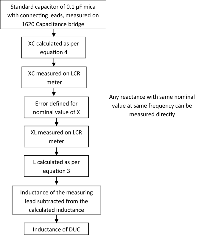
I = V XC I = V X C, where V is the rms voltage and XC is defined (As with XL, this expression for XC results from an analysis of the circuit using Kirchhoff’s rules and calculus) to be. XC = 1 2πfC X C = 1 2 π f C, where XC is called the capacitive reactance, because the capacitor reacts to impede the current. Series RLC Circuit Example No1. A series RLC circuit containing a resistance of 12Ω, an inductance of 0.15H and a capacitor of 100uF are connected in series across a 100V, 50Hz supply. Calculate the total circuit impedance, the circuits current, power factor and draw the voltage phasor diagram. Inductive Reactance, XL. Capacitive Reactance, XC. 1. Click to select the chart that you want to insert axis label. 2. Then click the Charts Elements button located the upper-right corner of the chart. In the expanded menu, check Axis Titles option, see screenshot: 3. And both the horizontal and vertical axis text boxes have been added to the chart, then click each of the axis text boxes and. Oct 22, 2016 · Move the L over to the left hand side and, like magic, Voila! L = X L 2 π f. Rearranging to get the capacitance, if you start with: X c = 1 2 π f C. and multiply both sides of the equation by C, in order to put C in a less cumbersome place to work with, you'll get: C X C = 1 C 2 π f C.
This book is really great I recomended for those people who doesn't understand electronic, this book will help you to a technical level in analogical and digital electronice. If you are an engineer and you don't understand electronics i
When Xl=Xc, ∅=0; in this instance the circuit has only resistive behavior so we say it's purely resistive (pg. 1009) Label each part of Figure 33.16, (a), (b), and (c), as representing XL> XC, XL< XC, or XL =XC.
Our custom writing service is a reliable solution on your academic journey that will always help you if your deadline is too tight. You fill in the order form with your basic requirements for a paper: your academic level, paper type and format, the number of pages and sources, discipline, and deadline.
Note. Adding the named parameter flags = icase with icase:. will produce a mesh where all quads are split with diagonal \(x-y=constant\); will produce a Union Jack flag type of mesh; will produce a mesh where all quads are split with diagonal \(x+y=constant\); same as in case 0, except two corners where the triangles are the same as case 2, to avoid having 3 vertices on the boundary
To address a label that is a greater distance away, yet within 4 GB in either direction, the instruction can be used. Note that the following code allocates 4 GB of data. If that allocation were done in the section, then the executable file would contain the 4 GB of data. By allocating the data in the section, the program size is reduced by 4.
Electrical and Electronic Principles and Technology 3rd ed by John Bird.pdf
To calculate the capacitive reactance you must initially multiply 2xπxfxC and then divide the result by 1. Example: a capacitor of 320nF, has a frequency of 1kHz, which will be the capacitive reactance, to find it you must multiply 2x320xπx10 ^ -9 × 1000 = 0.002010624 and the result is divided as follows: 1 / 0.00064 = 497.36 Ohm.
The student should understand the following policy: ATTENDANCE: Attendance is mandatory and any absence must be for a valid excuse and must be documented. If the instructor is more than 15 minutes late, students may consider lab for the day cancelled. LAB RECORDS: The student must: 1. Perform the PreLab assignment before the beginning of each.
What is the phase angle between the voltage across and the current through a series RLC circuit if XC is 500 ohms, R is 1 kilohm, and XL is 250 ohms? A. 68.2 degrees with the voltage leading the current; B. 14.0 degrees with the voltage leading the current; C. 14.0 degrees with the voltage lagging the current
Deternmine and sketch the even and odd parts of the signals depicted in Figure 5. Label your sketches carefully. Figure 5: The continuous-time signal x(t). Solution Figure 6: Sketches for the resulting signals. 5
the voltmeter on the circuit in Figure 1.1. Using the voltage divider rule, one can clearly see that the voltage V out the circuit of Figure 1.1 (a) is given by (1.1) Now, to examine the loading effect of the voltmeter in Figure 1.1 (b), we must develop an equivalent circuit model for the voltmeter. Without going into the details
Figure 14.68 For Prob. 14.1. Chapter 14, Solution 1. 1 j RC j RC R 1 j C R ( ) i o + ω ω = + ω ω = = V V H H(ω) = 0 0 1 j j + ωω ωω, where RC 1 ω0 = 2 0 0 1 H ( ) + ωω ωω = H ω = ⎟ ⎠ ⎞ ⎜ ⎝ ⎛ ω ω − π φ=∠ ω = 0 tan-1 2 H( ) This is a highpass filter. The frequency response is the same as that for P.P.14.1.
CruiserMaxx Sugarbeets is a combination of Cruiser 5FS, Apron XL fungicide and Maxim 4FS fungicide. See individual product labels for use directions. NipsIt Inside $ /A = 20.00 to 22.50. 60 g a.i./ 100,000-seed unit. For application to seed only with accurately calibrated mechanical, slurry or misting equipment.
IXL is the world's most popular subscription-based learning site for K–12. Used by over 12 million students, IXL provides personalized learning in more than 8,500 topics, covering math, language arts, science, social studies, and Spanish. Interactive questions, awards, and certificates keep kids motivated as they master skills.
PHY2054: Chapter 21 19 Power in AC Circuits ÎPower formula ÎRewrite using Îcosφis the “power factor” To maximize power delivered to circuit ⇒make φclose to zero Max power delivered to load happens at resonance E.g., too much inductive reactance (X L) can be cancelled by increasing X C (e.g., circuits with large motors) 2 P ave rms=IR rms ave rms rms rms cos
The students are allowed to pick the shirt sizes that they want. To determine how many of each size shirt they should order, college officials look at the distribution from last year. The following table shows the distribution of shirt sizes selected last year: X F S 27 M 48 L 136 XL 120 XXL 39 a.)
All Mathematical Symbols such as basic math symbols and other different symbols used in Maths are provided here. Visit BYJU'S to learn the symbol name in Maths.
The phase voltages are all equal in magnitude but only differ in their phase angle. The three windings of the coils are connected together at points, a 1, b 1 and c 1 to produce a common neutral connection for the three individual phases. Then if the red phase is taken as the reference phase each individual phase voltage can be defined with respect to the common neutral as.
To perform the fault calculations the following information must be obtained: 1. Available Power Company Short circuit KVA at transformer primary : Contact Power Company, may also be given in terms of R + jX. 2. Length of service drop from transformer to building, Type and size of conductor, ie., 250 MCM, aluminum. 3. Impedance of transformer.
Problem 2.2 A two-wire copper transmission line is embedded in a dielectric material with εr = 2.6 and σ= 2×10⁻⁶ S/m. Its wires are separated by 3 cm and their radii are 1 mm each.
Generate link. Generated link: DMCA Policy
Bending Light 1.1.22 - PhET Interactive Simulations
In Inductive circuit, XL > Xc and current lags behind sour… View the full answer Transcribed image text : (b) Label the following figure as being XL > Xc, XL - Xc, or XL <XC- AV. max L Imax O XL > Xc XL = Xc O x < Xc x (c) Label the following figure as being XL > Xc, XL = Xc or XL Xc- + Imax AVmax i O X{ > Xc O = Xc Ox < xc X
Figure P2.33: Circuit for Problem 2.33. All lines are 50 Ωand lossless. (a) Calculate Zin1, the input impedance of the antenna-terminated line, at the parallel juncture. (b) Combine Zin1 and Zin2 in parallel to obtain Z ′ L, the effective load impedance of the feedline. (c) Calculate Zin of the feedline. Solution: (a) in · ¸ ′ = 2 =
How can I figure out if a particular latitude/longitude point is within a specific area, like Europe? There's no ready-made function that will do this based on just the area name, like "Europe". However, if you have the lat/lon coordinates that define the particular area that you're interested in, then you can use the gc_inout function.
XLS Editor is an extension that allows to create, edit and view any Microsoft Excel document in both XLS and XLSX format. It also handles the standard Open Office format ODS.












0 Response to "40 (a) Label The Following Figure As Being Xl > Xc, Xl = Xc, Or Xl < Xc."
Post a Comment